Quebec, 29 August 1907 · from the Royal Commission's report
Add No More Load
The largest bridge in the world fell because a gauge nobody was reading ran out. The engineers had the numbers that week, on paper, in their own hands. Here they are again, run in your browser from the pages they were printed on.
At the end of August 1907 the south half of the Quebec Bridge was a steel cantilever reaching out over the St. Lawrence, meant to carry a railway across an 1,800-foot span, the longest of its kind anywhere. On the afternoon of Thursday the 29th it fell into the river. Out of eighty-six men on the work only eleven escaped with their lives.
That sentence is from the Royal Commission that investigated the fall, and its report, printed in Ottawa in 1908, is the source for everything on this page.
Two days before, the engineer at the site had measured a lower chord of the anchor arm bent sideways, and the bend was growing. Around noon on the 29th the bridge's consulting engineer in New York sent this:
Theodore Cooper to the contractor, as printed on p. 91 of the report. The report's dateline reads "August 27, 1907", but its own narrative puts the sending on the 29th, after Cooper reached his office "shortly after 11 a.m.", and Cooper's testimony gives the Western Union endorsement "Sent … at 12.16 p.m." The dateline is a slip in the printed report.
It went to the contractor's office in Pennsylvania, not to the bridge. It sat there four hours. The obvious story is a late telegram. The report tells a stranger one, and the numbers in it are good enough to rerun. The men on the bridge who saw the bend were alarmed by it; the foreman, the inspector and Cooper's own inspector all said so. The men who decided to go on were reading a different number, and it said the chord was fine.
Two gauges on one chord
A bridge chord in compression is judged first by its stress: load divided by area, set against what the specification allows. The chord that failed, A 9-L, had a cross-section of 780 square inches, four steel ribs 54 inches deep side by side, tied together by light diagonal bars called lattice. On 28 August E. A. Hoare, chief engineer of the Quebec Bridge and Railway Company (the owner), wrote to Cooper that these panels were stressed to-day, approximately, about 7/10ths of their maximum
. On the 29th Deans, chief engineer of the contractor, wired Hoare that the chords now have much less than maximum load
. By that gauge the chord was fine.
The other gauge is the lattice. A straight chord needs almost nothing from it. A bent one does: the load no longer runs down the middle, and the lattice has to carry the sideways shear that keeps the four ribs acting as one column. On the day of the collapse the chord's own designer, Peter Szlapka of the Phoenix Bridge Company, did that calculation for the reported bend. The Commission printed it (p. 93):
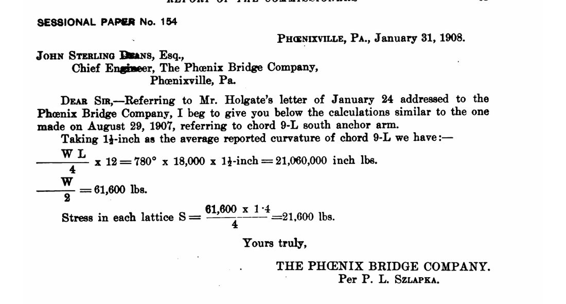
The Commission's comment is the whole story in one line: The theory underlying these calculations is very questionable, but it was adopted in the design of the bridge … and we cannot understand why its warning was so entirely disregarded in the face of the consequences that might result.
Move the bend and watch both gauges.
Instrument 1 · one chord, two gauges, Szlapka's arithmetic
Plan view of the 57-foot chord, four ribs and their lattice. The bend is drawn 12 times larger than life. At true scale it was small beside the chord, but not hidden: by 27 August the bends were very evident to one walking over them
, and the riveting gangs noticed them (pp. 87-88).
Chord stress is fixed at the Commission's figure for the moment of failure: 14,000,000 lb on 780 sq in, 17,950 lb/sq in, only three-fourths of the specified maximum working load
(pp. 125, 133), which for chords was 24,000 (p. 145). It does not move with the bend, and that is the point. The Commission's Drawing No. 13, the loading on 29 August, independently marks the chord panels beside the main pier at 17,560 and 17,910 lb/sq in. The rivet gauge runs Szlapka's formula above for whatever bend you set, divides the bar force by two ⅞-inch rivets (1.20 sq in), and compares it with the 18,000 lb/sq in the specification allowed rivets in shear. One honest caveat: the letter gives no rivet area. Two rivets is what the Commission's own sentence implies (the rivets were even then loaded to their maximum specified stress of 18,000 pounds per square inch
, p. 92), and the full-size rivet tests were run on pairs; but Appendix 16 lists 1.80 sq in (three rivets) for this chord's lattice bar, which would put Szlapka's 1½ inches at 12,000 instead. Either way the rivet gauge climbs with the bend while the stress gauge sits still.
What the Commission worked out afterwards
Szlapka's formula is a designer's rule. The Commission did a more careful version in Appendix 16, and it is sharper. Call the obliquity θ the small angle between the line of the load and the axis of the chord. The sideways shear is then S = Pθ, and the force in one lattice bar between the two centre ribs is 0.54 S (p. 129). Tests in Philadelphia showed the lattice rivets start to slip at about 50,000 lb per bar; three full-size lattice bars pulled apart at 60,100, 59,800 and 59,500 lb (pp. 119, 133, 135).
With P = 14,000,000 lb, slip arrives at θ = .0066 and the bars break at about .0079. From the measurements of 27 August the Commission reckoned the obliquity in the first lattice panel at .012 (p. 134). That is past both lines. So how was the chord still standing on the 27th? Because the ribs themselves were bending and carrying part of the shear, and the Commission computed how much: at .012 the bar force comes out at 51,264 lb (p. 135), just over slip, just under breaking. Thus if the obliquity = .0066 existed under a load P = 14,000,000 pounds, the chord would gradually go to destruction.
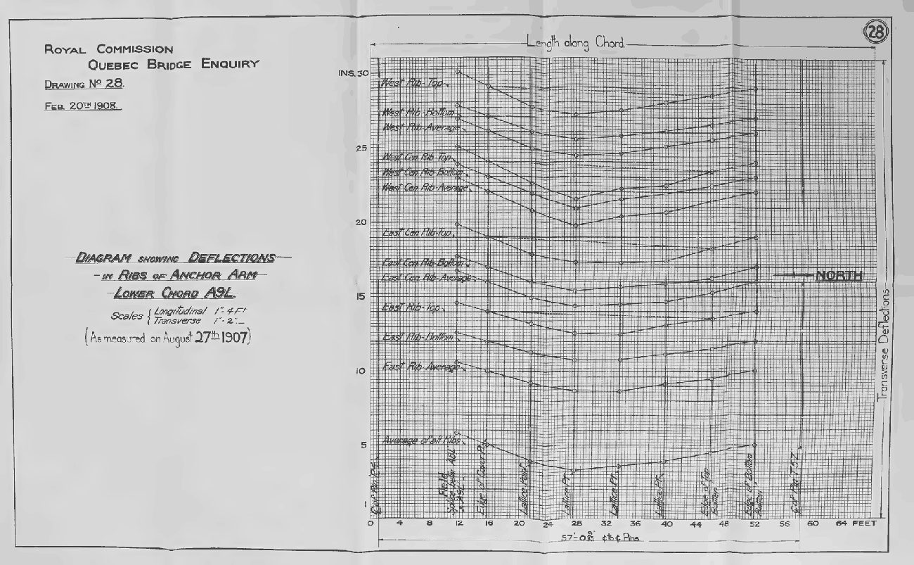
as measured on August 27th 1907, each rib's offset from a taut line, plotted along the chord (longitudinal scale 1 in to 4 ft, transverse 1 in to 2 in). The bottom curve is the average of all four ribs. The drawing prints no figures beside its points; the Commission's reading of it is
a deflection of the chord as a whole of 1¾ inches(p. 133).
Instrument 2 · the Commission's obliquity analysis (Appendix 16)
The straight line is 0.54 × 14,000,000 × θ, the bar force if the ribs stay straight and the lattice alone carries the shear. The rib-bending relief is not a general law: the Commission computed it from the curvature measured on 27 August (a radius of about 10,000 inches), so the toggle shows the one state it describes, at θ = .012. The ½-inch figure is the Commission's own allowance for a possible bend already in the chord (p. 134).
The weight nobody recomputed
Before the bend there was the weight. Designing a bridge is circular: you size each member for the load, but the members are much of the load. So a designer guesses the weight, sizes the members, weighs what he has drawn, and goes round again until the two agree. The Commission found that the second pass was never made. The members of the anchor arm had been sized for dead loads worked out in 1904. When the weights were finally determined on 25 June 1907, they were these (p. 57):
| Part | Designed for (lb) | Actual (lb) | Heavier by |
|---|
Cooper learned of it from a report on material dated 1 February 1906, when the anchor arm, a tower and two panels of the cantilever arm were already made. He estimated the error raised the unit stresses from seven to ten per cent
, judged them still safe, and let the work go on (p. 58). The Commission's finding (h) is blunt: the error was of sufficient magnitude to have required the condemnation of the bridge, even if the details of the lower chords had been of sufficient strength
. It did not by itself bring the bridge down that August; it made the margin thinner.
The chord, rebuilt at one-third scale
The Commission did not rest on formulas. In November 1907 the Phoenix Bridge Company built a one-third-scale model of the chord, 86.5 square inches of section, with its lattice to scale, and loaded it in a testing machine. A slip in signalling to the pump sent the load past the intended 25,500 to 26,850 lbs. per square inch, at which stress the member suddenly failed
, by shearing of the majority of the lattice rivets at the central panel
(p. 116). William Burr, the consulting engineer Phoenix engaged to run the test, then corrected that figure for the machine's friction (17½ per cent) and for the smaller rivets (0.86), and got 19,014 lb/sq in, which he called nearly identical
with the stress in the real chord when it fell (p. 117). The arithmetic checks: 26,800 × 0.825 = 22,110, and 22,110 × 0.86 = 19,014.
Then the Commission ran a test of its own. The testing machine could not take a full model with stronger lattice, so it built a smaller specimen: two ribs instead of four, each one-third the size of the chord's outer ribs, 11 ft 4½ in between pins, with lattice about twice as strong as the first model's. It failed at 37,000 lb/sq in by the buckling of the webs in the centre bay, the latticing being sufficiently strong
(p. 119). The Commission is careful about what that shows: the first model showed that the lattice system was too light, but gave no indication of the ultimate strength of the column if properly latticed
, and 37,000 is more than the real chord would have carried even if properly latticed
(p. 136). What it does show, in its words: The lattices of model chord No. 2 were proportionately only 50 per cent heavier than those used on the Quebec chords and yet they did not fail until the webs yielded
(p. 137). With enough lattice the ribs failed as ribs. Without it, the lattice went first.
One more fact from the drawings makes it concrete. The first chord of the anchor arm, A 1-L, had 301 square inches of section; A 9-L, the one that failed, had 781. Both members had about the same outside dimension in cross section, and the same latticing
(p. 140). The same lattice served a chord with two and a half times the section.
Three weeks of letters
None of this was hidden. The bends were noticed, measured, argued over and reported for more than three weeks before the fall. A selection from the record, each line with the page it is on:
Read in order, the letters are mostly careful people explaining the measurement away. Deans, on 12 August: The bend was no doubt put in the rib in the shop
. Cooper, on 26 August, after a theory of his own about a blow from a swinging beam came to nothing: This only makes the mystery the deeper
. Birks, the Phoenix company's engineer at the site, who knew how carefully the calculations had been made, could calculate that the stresses were then far below the expected maximum
, and the Commission is fair to him: To engineers the force of such reasoning is very great, and we do not consider that the confidence Mr. Birks placed in his superiors was in any way unusual or unreasonable
(p. 87). The calculation said the chord was well within its limit. It was. That was never the question.
Could the telegram have saved it?
Not the bridge. The Commission says so in finding (i): We do not believe that the fall of the bridge could have been prevented by any action that might have been taken after August 27, 1907.
Its tests satisfied it that no temporary bracing such as that proposed by Mr. Cooper could have long arrested the disaster
(p. 93). But finding (j) is the other half: The loss of life on August 29, 1907, might have been prevented by the exercise of better judgment
. The bridge was already lost when the telegram was sent. The men on it were not.
The telegram is also less simple than the legend makes it. The report says Cooper wired Phoenixville instead of Quebec because he thought action would be more promptly secured
that way, and that he did not know erection was going on, Mr. McLure having advised him to the contrary
. McLure had promised to wire Kinloch at the bridge with Cooper's decision, and did not (p. 91). Deans, in Phoenixville, knew he held later news from the bridge than Cooper did, and so waited for McLure, and then for Birks' letter of the 28th, before acting (p. 93). But Cooper's own testimony in the evidence volume has McLure telling him they are going on this morning to erect more of the work
. The report and the testimony do not agree on what Cooper knew, and this page does not settle it.
The Commission's findings
Signed at Montreal, 20 February 1908, by Henry Holgate, J. G. G. Kerry and John Galbraith. Five of the fifteen, verbatim (pp. 9 to 10):
The collapse of the Quebec bridge resulted from the failure of the lower chords in the anchor arm near the main pier. The failure of these chords was due to their defective design.
The failure cannot be attributed directly to any cause other than errors in judgment on the part of these two engineers.
(Szlapka, who designed the chords, and Cooper, who approved them.)These errors of judgment cannot be attributed either to lack of common professional knowledge, to neglect of duty, or to a desire to economize. The ability of the two engineers was tried in one of the most difficult professional problems of the day and proved to be insufficient for the task.
We do not consider that the specifications for the work were satisfactory or sufficient, the unit stresses in particular being higher than any established by past practice. The specifications were accepted without protest by all interested.
The professional knowledge of the present day concerning the action of steel columns under load is not sufficient to enable engineers to economically design such structures as the Quebec bridge.
That last one is the rarest sentence in the report: an official inquiry saying that part of the answer was not known yet. Built-up compression members like this chord were then designed by formulas that, as the Commission showed in a table on p. 132, disagreed about the lattice this chord needed by a factor of nearly ten (from 0.75 to 7.04 square inches of bar).
What the retellings say, against the record
The collapse is a standard case in engineering ethics courses, and the story has worn smooth in the retelling. Some of it holds. Each line below quotes a published retelling (fetched 26 September 2026) beside what the 1908 report prints.
| The retelling | The record |
|---|---|
In order to cut the cost of building the piers farther out in the river, Cooper lengthened the bridge span(The Canadian Encyclopedia, "Quebec Bridge Disaster") | Cooper's report of 1 May 1900 gives three reasons: the deeper piers of the 1,600-foot span would take at least one more year; deep-water piers risked the heavy ice floes of the main channel; and a shorter schedule would help future financing. He estimated the change would add $200,000 (p. 17). Cheaper piers, dearer bridge. |
The commission found that the stresses on the bridge members had not been recalculated after Cooper increased the span length.(ENR) | The span was fixed at 1,800 feet in May 1900. The weights the members were sized for came from Szlapka's diagram of 12 May 1904, for the 1,800-foot design. What the Commission faults is that those weights were never recomputed from the members once they had been drawn (pp. 57-58). Not recalculated, yes; but not a leftover from the shorter span. |
Place no more load on Quebec bridge until all facts considered. Deans had read his wire but ignored it.(The Canadian Encyclopedia) | The report prints Add no more load to bridge till after due consideration of facts.Deans read it about 3 p.m., arranged for Szlapka and Milliken to meet McLure, but otherwise took no action, because he believed he held later news from the bridge than Cooper did (pp. 91, 93). The report's word is judgment, not ignoring. |
Cooper … never visited the project once construction commenced on the superstructure.(ENR) | This one holds. The report: Cooper was rapidly approaching seventy, rarely allowed to leave New York, visited the site several times while the piers were building and not during erection of the steel (pp. 49-50). |
the loss of 76 lives in 1907(the federal plaque, Parks Canada; also the Corporation of the Seven Wardens); 75 in The Canadian Encyclopedia and Wikipedia; 74 in ENR. | Out of eighty-six men on the work only eleven escaped with their lives(p. 96): 75. The report does not print the number, and this page did not find the source of the 76th. Most retellings say 33 of the dead were Mohawk ironworkers from Kahnawake (Wikipedia adds some sources say 35); the report prints no list of the dead and gives no such figure. |
| Canadian engineers' iron rings were made from the wreck of the bridge. | The Corporation of the Seven Wardens, which administers the ring: Contrary to a common misunderstanding, the iron rings are not made from the failed Quebec Bridge that spans the St. Lawrence River.The ritual began in 1925. The collapse is part of its history; the metal is not. |
After the report, not in it: on 11 September 1916 the rebuilt bridge's centre span fell while being lifted into place, when a casting failed
, killing 13; a new span went up on 20 September 1917 and a ceremonial train crossed on 17 October 1917 (the Canadian Society for Civil Engineering). Its 1,800-foot span (549 m) is still the longest cantilever span in the world; the Forth Bridge's two 1,710-foot spans come next.
The check
- Every number above is recomputed in your browser by one small file, quebec.js, from inputs printed in the report, and each constant in it names its page. The instruments on this page are that file running.
- What the check reproduces: the moment 780 × 18,000 × 1.5 = 21,060,000 in-lb and the lattice force 21,552 lb against Szlapka's printed 21,600 (his rounding; his chord length is not printed, and 57 ft, the length on p. 139, gives back his 61,600 end shear to 0.03%); θ = .0066 at slip; .0079 at breaking; 168,000 and 146,468 and 51,264 lb for 27 August exactly as printed on p. 135; the dead loads 17.6%, 19.7% and 30.0% heavier, 23.8% overall; Burr's 22,110 and 19,014; the model's failing load 2,322,600 lb over 86.526 sq in = 26,843, against the machine's 26,850.
- Run it yourself: node verify-why-did-the-quebec-bridge-collapse.mjs in an empty folder downloads this page and its engine from the site, re-derives each figure from the report's inputs, checks the page's prose against them, and then breaks the engine seven ways on purpose to show each break is caught (the script).
- What was read, and how: the report was read from the page images of the Internet Archive scan, not from its OCR, which garbles fractions (it renders ¾ as "j" and 2¼ as "2J"). Where a figure rests on the OCR alone it is not used.
- What is not settled here: the rivet area behind Szlapka's 21,600 lb (see the caveat under Instrument 1); the clock time of the fall, which the report does not print (a witness says 5.31, a Phoenix telegram 5.30); whether Cooper knew erection had resumed; the chord-bend drawings (28 to 30) plot the 27 August measurements as points without printing figures beside them, so the bends used here are the ones the report prints in words (¾, 1½, 1¾, 2¼ inches). Read off Drawing 28 by machine at 300 dpi, the plotted points give an all-rib average near 1.7 inches and one rib near 2.3, consistent with those words; that reading is ours, about ±0.1 inch, and is not used in any number above. The report's list calls Drawings 28 to 30 the bends of 6, 12 and 27 August; on their faces the three main plots are dated 27 August, and Drawing 30 carries an inset of the 7-L/8-L splice
as measured on Aug 6th & Aug 16th 1907
. - What this page is not: a structural analysis of its own. The obliquity model, the rivet slip load and the rib-bending relief are the Commission's, used as they used them. The page reruns their arithmetic and shows it holds; it does not claim their theory of latticed columns is the modern one.