Plumbing · pressure · an outbreak in Hong Kong
The Water Between You and the Sewer
The bend under a sink keeps a plug of water, and that water is a pressure gauge: in a simple model, a seal of depth t gives way to suction from the drain at t and to back pressure at 2t. Pull past t and it spills over its own weir, settles at half, and then holds; Bureau of Standards engineers reported the same half in the 1920s, and the losses they computed for five brass traps in 1951 come to 45% to 52% of each trap's seal. What the model cannot say is where the pressures come from, or what happens when nobody runs the tap, as in the floor drains of Amoy Gardens in 2003.
Every sink, bath, shower and floor drain reaches the sewer through a pipe that dips and rises again, and the dip keeps water. In 1951 the US National Bureau of Standards put the purpose of that water in two sentences:
The purpose of the trap is to interpose between the sewer and the interior of the building a water seal that will prevent sewer air from passing back into the building and causing offensive odors there. This water seal is normally from 2 to 4 inches in depth and is sufficient to prevent the passage of sewer air into the building under any ordinary conditions.
Foreword, signed E. U. Condon, Director, to J. L. French and H. N. Eaton, Self-Siphonage of Fixture Traps (NBS BMS126, 1951), p. III
England's building guidance, Approved Document H (2015 edition), lists a 75 mm seal for a washbasin or sink and 50 mm for a bath, shower or WC pan. The depth runs from the lip the water spills over, the weir, down to the dip, the level where the seal ends: with the water down to the dip in both legs, French and Eaton wrote, minute changes of pressure in the proper direction will suffice to force sewer gas into the building
. A later Bureau monograph defines the depth in words it took from the American Standard National Plumbing Code of 1955: The trap seal is the maximum vertical depth of liquid that a trap will retain, measured between the crown weir and the top of the dip of the trap.
Read that water as a U-tube pressure gauge and the trap becomes something you can push on. A column of water holds back a pressure equal to its own weight per unit area: by the conventional definition, 1 mm of water is 9.80665 pascals.
Push on the sewer side
A trap, to scale, and the pressure in the drain
Move the slider to pull or push on the water.
Drawn to scale: the water heights on screen are proportional to the millimetres in the readout. The model is quasi-static: both legs the same width, the pressure held still until the water settles, no inertia.
Three things happen, and the readout names each as you drag. Pull, with suction from the drain side, and the room-side water falls while the drain-side water rises, but the drain-side leg is already full to its weir, so the rise spills over and is gone; let go and the two legs settle level and lower, so a pull of s leaves a seal of t − s/2. Pull as far as t and the room-side water reaches the dip, air goes through, and what is left settles at exactly half. Push, with back pressure, and the drain-side water falls while the room-side water rises into the fixture, nothing spills, and sewer air bubbles into the room only when the push reaches 2t. For a 50 mm seal that is a pull of 50 mm of water (490 Pa) and a push of 100 mm (981 Pa).
This is the simplest model true to the geometry, and it shows where the water ends up, not how it sloshes on the way. Real losses happen in transients, in the moments as a basin finishes emptying or as other fixtures discharge into the same pipes. The 1951 report that studied them called the problem an extremely complicated problem, one which defies analytical treatment
, and turned to experiments and dimensional analysis instead.
It stops at half, and remembers
The surprise in the model is not the break. It is what comes after. Water pushed over the weir does not come back, so the trap is a one-way ratchet: every pull that spills lowers the seal for good, and in the model nothing raises it again except fresh water from the fixture. Pull your trap, then pull it again just as hard.
Repeated pulls on one trap (the seal chosen above)
seal leftsuction it can takeback pressure it can take
No pulls yet.
Whatever the size of the pull, the first one does all the damage. A pull of s smaller than t takes s/2 and leaves the drain-side leg filled exactly to the height where that same pull no longer spills; a pull of t or more leaves t/2, and from then on the trap is a plain U-tube that no steady pull can lower further. What changes is its strength in the other direction. A full seal withstood back pressure up to 2t; a half seal withstands only t. One hard pull halves the trap's defence against the push that drives sewer air into the room.
Engineers at the US Bureau of Standards had already reported the same half. In the Bureau's plumbing report revised in 1928, R. B. Hunter and L. W. Snyder wrote:
An S or a P trap seal may be drawn to the point of breaking the seal with a loss of approximately one-half its full seal, after which it may be subjected repeatedly to the same or a smaller strain with no further loss of seal.
R. B. Hunter and L. W. Snyder, Physics of plumbing systems, chapter 6 of Recommended Minimum Requirements for Plumbing (Bureau of Standards, revised August 30, 1928), p. 137
In 1951 John French and Herbert Eaton gave the mechanism. Let the room-side water fall to the dip, they wrote, and The water thus displaced flows over the trap weir and down the drain, and thus is not available to refill the trap when the pressures on the two sides of the trap seal equalize.
They named what is lost the critical trap-seal loss. They knew the half too: they credit One investigator
with proposing one half as the dividing line between satisfactory and unsatisfactory traps, citing page 137 of the Bureau's 1924 Recommended minimum requirements for plumbing in dwellings and similar buildings. And when they weighed how safe a reduced seal is, the pressure they said would need studying was a positive pressure equal in magnitude to twice the remaining trap seal
.
The model's floor at half has an exception they stated. The loss can go further if the suction becomes and remains for an appreciable length of time so excessive
that air is sucked through the seal, carrying water with it by what may be called a pumping process
. The model holds each pull still and has no such process, so it shows the ratchet, not that limit.
Real traps are not straight tubes
In the model the half is exact because the two legs are identical. A real P-trap joins a U-bend of one radius to an outlet bend of another, and French and Eaton worked out what that does for the five brass traps they tested. They treated the outlet leg between the two bends as a cylinder and simplified one step of the working by treating the two radii as equal: By making the assumption that these two radii are equal, a considerable simplification in the computations results
. The critical loss that comes out still keeps the two radii apart: hc = (t − ru − ro)/2 + ro, where ru is the radius of the lower bend and ro that of the upper one. The table recomputes it, in your browser, from the radii printed on their page 10.
French and Eaton's five traps, recomputed
All lengths in inches, as printed. The radii and seals come from the page image; the data file is nbs1951.json, served beside this page.
Across the four computed rows, the spread away from one half comes from one term: hc is t/2 plus half of (ro − ru). An outlet bend tighter than the U-bend takes the loss below half. The 1½-inch drawn brass tubing trap's outlet bend is 9/32 inch tighter than its U-bend, so it loses 46.1% of its seal, not 50%. Press the button and every computed row goes to exactly 50%. The fifth trap's 1.18 inches is French and Eaton's own estimate, from the volume of part of a torus; the page shows it but does not recompute it, and on that trap's 2.25-inch seal it is 52.4%.
Two slips in the 1951 arithmetic
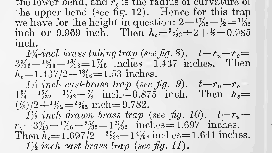
Recomputing the table from the printed fractions turns up two decimals that do not match their own fractions. For the 1½-inch drawn brass trap the print reads 1 23/32 inches = 1.697 inches, but 1 23/32 is 1.71875. The slip did not travel: the next step, 1 41/64 inches = 1.641 inches, is what 1 23/32 gives, while 1.697 would have given 1.630. For the 1¼-inch cast-brass trap, 25/32 inch is printed as 0.782, but it is 0.78125, which rounds to 0.781. The other two rows seem to round from an already-rounded step (0.985 where the fractions give 0.984375) or drop a digit (1.437 for 1.4375). None of this moves a share of the seal by as much as a tenth of a percentage point. The page image above is the authority here; the scan's machine-read text garbles these fractions.
Where the pressure comes from
Everything so far takes the pressure as given, and hydrostatics has nothing to say about where it comes from. It comes from water falling past. The 1961 Bureau monograph on drainage stacks puts the cause in two sentences:
The principal cause of air movement in building drainage systems is the friction developed between the high-velocity layer of water flowing down the drainage stack and the core of air which it encloses. The friction thus developed drags air along with the water.
R. S. Wyly and H. N. Eaton, Capacities of Stacks in Sanitary Drainage Systems for Buildings (NBS Monograph 31, 1961), p. 19
Water running down a vertical stack carries air down with it. Hunter and Snyder had mapped the result with pressure gauges up and down their test stacks:
In all cases back pressures only were encountered at the base of the stack. The region of back pressures extended upward as the volume of the discharge was increased. In the upper portions of the stack below the entrance point of the discharge partial vacuums only were encountered. Between these two is a region in which the pressure alternates between positive and negative pressures measured from atmospheric pressure as the zero.
Hunter and Snyder, in Recommended Minimum Requirements for Plumbing (1928), p. 110
One stack: where the water comes in, and where your trap is
partial vacuum (suction)back pressurealternates, or either, depending on flowno measurable effect above the inflow, very slight at it (stack top open)
Colours mark the sign of pressure the sources report for a position, not its size, and the boundaries between them are not to scale. The signs are for a branch with no vent of its own.
The map is only signs, because these sources give no general rule for where one region ends. Hunter and Snyder found the back-pressure region moving up as the flow grew, and the 1961 monograph agrees on the two ends and adds why no single map will do: Least pressures occur immediately below a point of water entrance, and greatest pressures occur near the base of the stack. The pressure at any point is a function of rate of discharge, elevation of point of water entrance, degree of venting, and geometry of the system.
In the region between, Hunter and Snyder found the pressure alternating, so a trap there can be pulled one moment and pushed the next. Two conditions go with the map. For a 3-inch stack vented only through its open top, Hunter and Snyder noted that their readings were not necessarily those in the center of the stack, but rather the pressures that would be produced in an unvented branch line connecting at that point
. And their measurements at points on the stack above the inlet through which water was introduced into the stack showed no measurable effects when the stack top was open
.
How hard can the stack pull? In one of Hunter and Snyder's tests, a 3-inch stack 33 feet long, vented only through its open top, took water at 200 gallons a minute, and The maximum of any individual pressure reading was 31.3 inches of water vacuum at the point 10 inches below the entrance point.
That is more than fifteen times the suction a full 2-inch seal can take. Vents exist to stop it. Hunter and Snyder worked out vent sizes from the assumption that no positive or back pressure greater than 1 inch and no negative pressure or partial vacuum less than 1 inch of water, measured from atmospheric pressure as the zero, is to be developed in any branch drain connecting to the stack above the house drain
. In 1961 the monograph described the vent tables in most plumbing codes as meant to keep pressures at critical points within plus or minus 1 inch of water column, and added: If this range of pressure can be maintained, the effects of pneumatic-pressure fluctuations on the fixture-trap seals will be negligible.
In the model, a 2-inch seal pulled by 1 inch keeps 1.5 inches, and then needs 3 inches of back pressure before sewer air bubbles through. That band belongs to these US studies and the vent tables they describe; it is not a universal rule. England's Approved Document H states its rule as a seal kept, not a pressure: Under working and test conditions traps should retain a minimum seal of 25mm of water or equivalent.
In the model, back pressure that wins pushes sewer air through the water and the water falls back afterwards; it is suction that lowers the seal, which is why the half-strength trap matters. Hunter and Snyder's test logs name what they saw in words like these: Blown
, which means water thrown up from the closet bowl or out of the bowl by back pressure
, and Bubble
or bubbles
, which means a small quantity of air forced back through the trap by back pressure
. The 1951 foreword joined the two halves of this page in one sentence: However, if, through self-siphonage or any other cause, part of the water seal in the trap is lost, then the pressure fluctuations in the drainage system of the building, which occur as the result of the discharge of the fixtures on the system, may be great enough to bubble sewer air back through the trap seal.
The failure that needs no flow
There is a way to lose a seal with no pressure at all. Water evaporates, and a trap nobody uses is never refilled. The 1928 committee already counted it among the reasons a seal needs a margin: some factor of safety must be allowed to provide for unexpected shocks, for evaporation, capillary loss, and for oscillations due to wind pressure
.
The figure for how fast is old. J. J. Cosgrove's Principles and Practice of Plumbing (1906), working from experiments by a Dr. Unna, municipal engineer of Cologne, gave a rule for unvented traps: the rate of evaporation will average .4 of an inch per week, irrespective of size or shape of the surface exposed
. For vented traps he had no data, but thought it would be safe to assume a rate of .8 of an inch per week
. His own worked example, a 1¾-inch seal destroyed in from four and a half to five weeks' time
, implies 0.35 to 0.39 inch a week, so treat the rule as a rounded guide from 1906, not a measurement of anyone's bathroom. The slider starts at his 0.4 inch, which is 10.16 mm, a week; set it to whatever you believe.
A trap nobody uses (the seal chosen above)
A fan that lowers the room's pressure acts on the trap exactly like back pressure from the drain: what the water feels is the difference. The Amoy Gardens reports give no figure for how far the fans pulled; that slider is yours.
Any water at all stops air while the pressure difference is small; a dry trap stops nothing. Once the seal is gone the trap is an open pipe, and whatever pulls the room below the drain draws sewer air straight in. Hong Kong's Buildings Department put the risk in one sentence, in a practice note first issued in June 2003 and quoted here from its re-issue of August 2009: The water in the trap may dry up through evaporation unless water is replenished, from time to time, by the occupants or through discharge of waste water.
Amoy Gardens, 2003
SARS broke out among the residents of Amoy Gardens, a private housing estate in Kowloon Bay, Hong Kong, towards the end of March 2003. By the Department of Health's count, As of 15 April 2003, there were a total of 321 SARS cases in Amoy Gardens.
Block E held 41% of them. Hong Kong's SARS Expert Committee later gave the final toll: At the end of the outbreak, a total of 329 residents had been infected, with 42 deaths.
The blocks were plumbed the way this page has been describing. Each block has eight vertical soil stacks each collecting effluent from the same unit of all floors. The soil stack is connected with the water closets, the basins, the bathtubs and the bathroom floor drains.
Each of those fixtures had a U-trap, and the Department's report of 17 April 2003 set down the condition in one line: For this preventive mechanism to function properly, the water traps must be sufficiently filled with water.
The Department reasoned that the toilets, basins and baths were used often enough to keep their traps charged, but that the floor drains were another matter: as most households had the habit of cleaning the bathroom floor by mopping instead of flushing it with water, the U-traps connected to most floor drains were likely to be dry and would not have been functioning properly
. Likely, not measured: the report gives no seal depths. A test in one Block E flat showed what such a drain does: reflux of air from the soil stack into the bathroom through the floor drain was demonstrated when the exhaust fan in the bathroom was switched on
. Under the heading PROBABLE EXPLANATION OF THE OUTBREAK
, the Department wrote:
The bathroom floor drains with dried-up U-traps provided a pathway through which residents came into contact with small droplets containing viruses from the contaminated sewage. These droplets entered the bathroom floor drain through negative pressure generated by exhaust fans when the bathroom was being used with the door closed.
Department of Health, Hong Kong, Outbreak of SARS at Amoy Gardens: Main Findings of the Investigation (17 April 2003), para 15
A month later an independent WHO environmental health team reached a similar view:
At the time of the outbreak, the floor drain traps in many apartments seemed to have not been filled with water for long periods. Thus they had lost their sealing function and generated an open connection to the soil stack. In the case of a running exhaust fan and a closed door, droplets would have been drawn from the soil stack into the bathroom through the floor drain.
WHO Environmental Health Team, report on Amoy Gardens (released 16 May 2003), Conclusions
Neither report makes the drains the whole story. The Department's probable explanation also names person-to-person contact and the use of shared communal facilities such as lifts and staircases
. The WHO team's concluding remark reads: It seems highly likely that an unfortunate sequence of environmental and health events happened simultaneously and contributed to the spread of the SARS-related coronavirus in the Hong Kong residential estate of Amoy Gardens.
The Government's press release that day reported the Deputy Director of Health, Dr Leung Pak-yin, noting that both investigations pointed to a combination of events
.
Two things the reports do not settle
Airborne? The Department of Health, 17 April 2003
Transmission of the disease by airborne, waterborne route and infected dust aerosols have been examined but these were not supported by the epidemiological picture and laboratory results.
The same report postulates that droplets from the soil stack, drawn by bathroom exhaust fans into the light well, could then enter other units through open windows
.
Airborne? Yu and colleagues, New England Journal of Medicine, 2004
They examined the correlation of these data with the three-dimensional spread of a virus-laden aerosol plume that was modeled using studies of airflow dynamics
, and concluded: Airborne spread of the virus appears to explain this large community outbreak of SARS
.
The cracked vent pipe: the Department of Health
Tests found a large crack in a sewer vent pipe at the fourth floor of Block E. The cracked sewer vent pipe could have emitted droplets carrying contaminated sewage into the light well every time a toilet was flushed.
The broken vent pipe: the WHO team
There is no strong enough evidence to link the broken vent pipe discovered at the bottom of the light well to the spread of the virus.
Neither report says whether the two describe the same pipe.
This page does not choose between them. What the plumbing can say is narrower: a trap that has dried out holds back nothing, and in the Department's own test a running exhaust fan drew air from the soil stack up through a floor drain.
The route through drainage stacks was studied again in 2020, when a team in Guangzhou investigated nine people infected with SARS-CoV-2, in three families who lived in vertically aligned flats connected by drainage pipes. Their abstract lists as a limitation the Inability to determine whether the water seals were dried out in the flats of the infected families.
Part of the advice that followed Amoy Gardens was plain plumbing: residents were advised to ensure the water level at the U-traps of drainage outlets to ensure proper functioning
, and the Buildings Department suggested that building designers consider diverting some waste water from another fitting into the floor-drain trap, so that nobody has to remember to top it up.
Hydrostatics is right about the seal: a column of water t deep holds t of suction and 2t of back pressure, and after one hard pull it is half as deep and holds t either way. It is silent about the threat. The pressures come from falling water and from fans, and the seal failure that both official accounts point to at Amoy Gardens needed no pressure at all, only long periods without water.
The check
Apart from the date the sources were fetched, each figure on this page is either computed or taken from a named source. The computed ones come from engine.mjs, in your browser, working from the model above and from nbs1951.json (the five traps as printed). One program you can run recomputes them independently and holds every sourced figure to the sentence that states it:
curl -sO https://artwaste.land/checks/verify-the-water-between-you-and-the-sewer.mjs
node verify-the-water-between-you-and-the-sewer.mjs
It downloads this page and its files (index.html, engine.mjs, nbs1951.json, quotes.json) and:
- steps the water through every pull and push on a grid of seals and pressures with its own volume bookkeeping, sharing no code with the engine, and checks the break at t, the settling at t − s/2, the floor at t/2 and the back-pressure break at 2r;
- recomputes four of the five traps from fractions typed into it from the page image of the 1951 report, checks French and Eaton's printed estimate for the fifth, and recomputes the two slips;
- recomputes the unit conversions and the evaporation times;
- finds every figure in the prose in its own sentence, and fails on any number on the page that it has not checked or declared;
- checks every quotation against the source passage in
quotes.json, and the description copies in the page head against the visible summary.
With --mutate it plants six wrong figures in a copy of the page and one in a copy of nbs1951.json, and must fail. The free choices, named: the quasi-static model (equal legs, no inertia, pressures held still); the conventional millimetre of water, 9.80665 Pa; a uniform evaporation rate that you set; a stack map of signs, not sizes; and NBS's own estimate for the fifth trap. What the program cannot check: that the fractions were read correctly from the 1951 page (the scan is above, so read it yourself), and that each source says what its excerpt says (the links are below). The Amoy Gardens reports give no fan pressures and no seal depths, and this page invents neither.